KUHN RIKON Corp. Drill 30-100 User Manual
Browse online or download User Manual for Power tools KUHN RIKON Corp. Drill 30-100. Kuhn Rikon Corp. Drill 30-100 User's Manual
- Page / 24
- Table of contents
- TROUBLESHOOTING
- BOOKMARKS
Summary of Contents
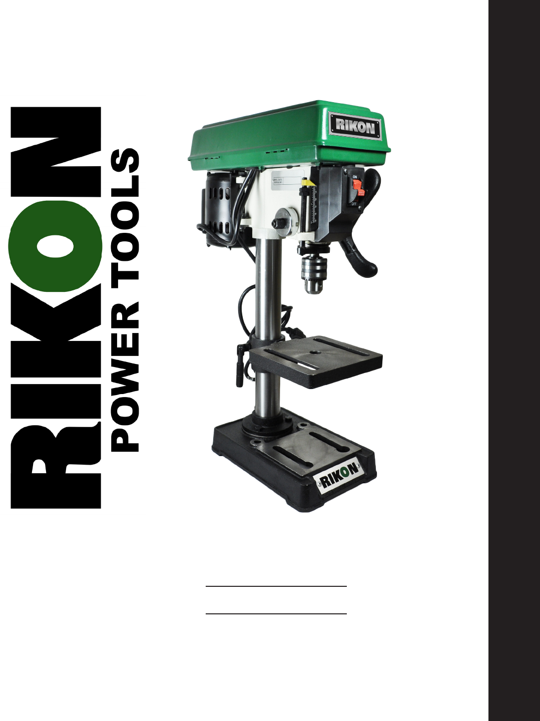
8” Bench Drill PressModel: 30-100 Owner’s ManualFor more information:www.rikontools.com or [email protected] Parts or Questions:techsupport@riko
Assembly10 Fig.0910. Loosen the motor lock knob (A-Fig.10). Move the motor (B-Fig.10) manually toward the feed
Troubleshooting11
Use this section to record maintenance, service and any calls to Technical Support:12NotesWARNING:This machine must be grounded.Replacement of the pow
In the event of a malfunction or breakdown, grounding provides a path of least resistance for electric current to reduce the risk of electric shock. T
Explosion Diagram14
Parts List15KEY No. Bushing-RubberKnobScrew-Pan Hd.M5x0.8-1.2Belt-”V” 5/16x26Guard w/LabelsScrew-Washer Hd.Ring RetainingBearing-Ball 17mmSpacerInse
Explosion Diagram18
KEY No. Gasket-QuillBearing-Ball 12mmTube-QuillScrew-Pan M5x0.8-20Collar-StopRing RetainingShaft-SpindleChuckKey-ChuckNut-Hex M6x1.0Nut-Hex M5x.08Ro
Safety WarningsIMPORTANT! Safety is the single most important consideration in the operation of this equipment. The following instructions must be fol
Explosion Diagram20
KEY No. Support-Table w/ScaleSupport-Lock HandleTube/SupportBaseScrew-Hex Hd. M8x1.25-20Screw-Hex Hd. 1/2-12x7/8Table30-100-1D30-100-2D30-100-3D30-1
5-Year Limited WarrantyRIKON Power Tools Inc. (“Seller”) warrants to only the original retail consumer/purchaser of our products that each product be
Notes
For more information:16 Progress RdBillerica, MA 01821877-884-5167 / 978-528-5380techsupport@rikontools.comwww.rikontools.comCopyright RIKON Power To
SAVE THESE INSTRUCTIONS.Refer to them often.3California Proposition 65 WarningWARNING: Some dust created by power sanding, sawing, grinding, drilling,
Table of ContentsSafety Warnings...
5Contents of PackageUnpacking and Checking ContentsItem Description1 Drill Press Head2 Base3 Table4 1/2” Chuck5
6Getting to Know Your Drill Press123678101112Item Description1 Base2 Table Lock Handle 3 Table4 Column Support
Unpacking and Clean-up1. Carefully nish removing all contents from shipping carton. Compare contents of the shipping carton with the list shown on p
8 Assembly3. Slide the drill press head over the column. (Fig.03)4. Center the drill press head over the
9Assembly6. The feed handle (A-Fig.06) is secured to the feed shaft with the supplied Allen bolt (B-Fig.06). Fig.0
© 2020, manymanuals.com. All rights reserved. | 0.479 s |
 Manymanuals.com
 Manymanuals.de
 Manymanuals.fr
 Manymanuals.it
 Manymanuals.pl
 Manymanuals.cz
 Manymanuals.es
 Manymanuals-pt.com
Comments to this Manuals